power factor correction circuit
|
Power Factor Correction (PFC) application notes Eaton
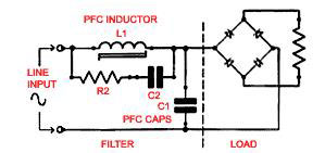
A passive PFC uses a filter at the AC input to correct poor power factor The passive PFC circuitry uses only passive components — an inductor and some |
|
Power Factor Correction (PFC) Circuit Basics PPT
–What is power factor correction (PFC)? –Why is it needed? –How is it measured? •Overview –Critical conduction mode (CrCM) •Compensation •Feed-forward •Sources of distortion –Continuous conduction mode (CCM) –Interleaved –Bridgeless 2 |
Power Factor Correction (PFC) lowers the current drawn by an electrical system.
It does this by producing the reactive power (KVAr) locally, thereby reducing the current drawn from the mains.
Ultimately, this means that less power is used so you save money and lower your carbon footprint.
How can you correct power factor in an electrical circuit?
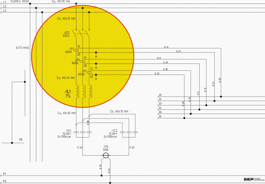
What can I do to improve power factor? You can improve power factor by adding power factor correction capacitors to your plant distribution system.
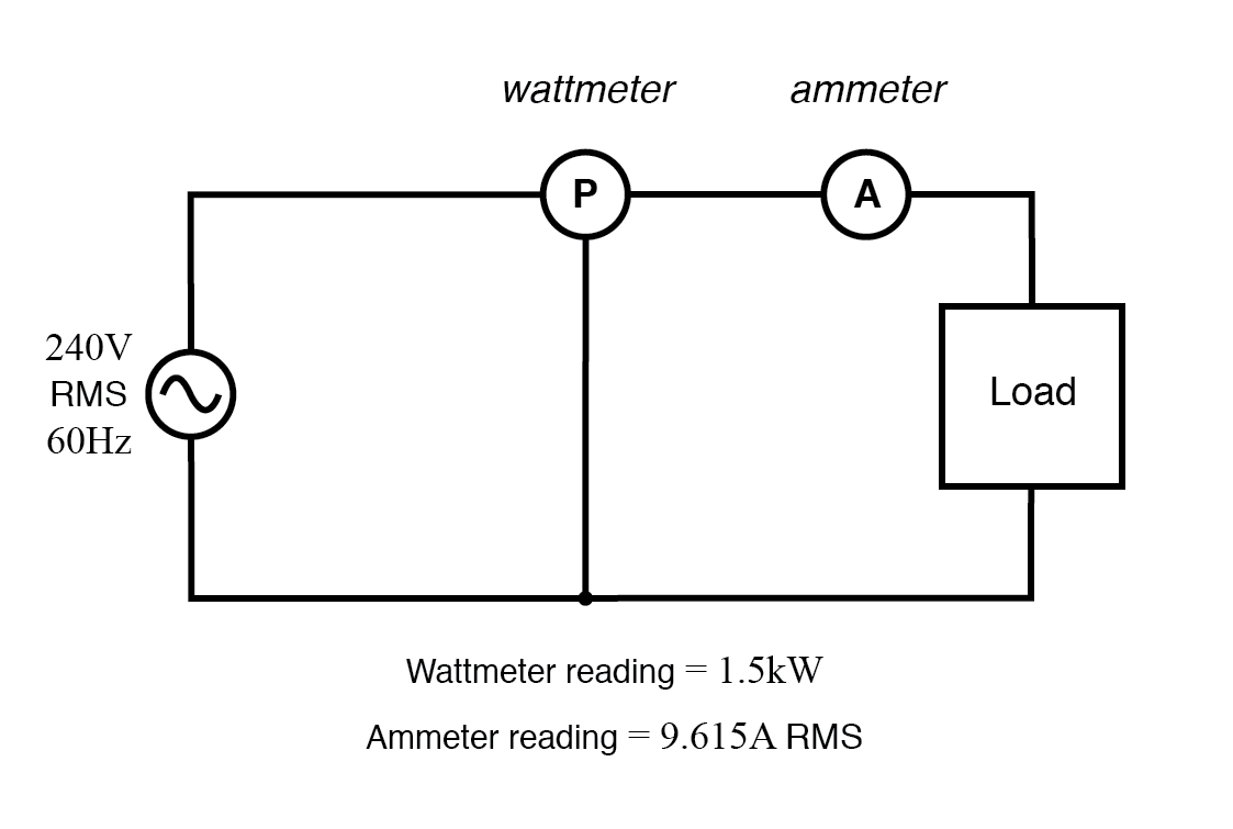
When apparent power (kVA) is greater than working power (kW), the utility must supply the excess reactive current plus the working current .
How do you calculate power factor correction?
Determining the PFC required
Qc can be determined from the formula Qc = P (tan φ – tan φ'), which is deduced from the diagram.
The parameters φ and tan φ can be obtained from billing data, or from direct measurement in the installation.
What is a power factor correction circuit in a rectifier?
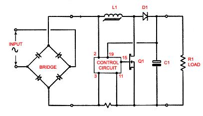
The PFC rectifier functions to adjust the zero crossings and peak occurrences of the input line current at the same instant as the input line AC voltage.
PFC rectifiers are usually semiconductor switch based AC-DC converters and have the flexibility of a wide output voltage range.
Power Factor Correction Example No1
An RL series circuit consists of a resistance of 15Ω and an inductor which has an inductive reactance of 26Ω. If a current of 5 amperes flows around the circuit, calulate: 1) the supply voltage. 2) the phase angle between the supply voltage and circuit current. 3) Draw the resulting phasor diagram. 1). The supply voltage VS We can double check this
Power in A Rl Series Circuit
In a circuit containing reactance, the current, i will either lead or lag the voltage by some amount depending on whether the reactance is capacitive or inductive. The power consumed by the resistor in watts is called the “real power” so is given the symbol “P” (or W). Watts can also be calculated as I2R, where R is the total resistance of the circ
Power Factor Correction Example No2
A coil has a resistance of 10Ω and an inductance of 46mH. If it draws a current of 5 Amperes when connected to a 100Vrms, 60Hz supply, calculate: 1) the voltages across the components. 2) the phase angle of the circuit. 3) the different powers consumed by the series RL circuit. First find the impedances 1). The voltages across the resistor, VR and
Power Factor Correction
Power Factor Correction improves the phase angle between the supply voltage and current while the real power consumption in watts remains the same, because as we have seen a pure reactance does not consume any real power. Adding an impedance in the form of capacitve reactance in parallel with the coil above will decrease Θand thus increases the pow

Power Factor Correction

Power Factor

Power factor correction
|
Power Factor Correction (PFC) Circuit Basics
A power factor correction (PFC) circuit intentionally shapes the input current to be in phase with the instantaneous line voltage and minimizes the total |
|
Power Factor Correction (PFC) Circuits
6 nov. 2019 A power factor correction (PFC) circuit is added to a power supply circuit to bring its power factor close to 1.0 or reduce harmonics. |
|
APPLICATION NOTE U-134
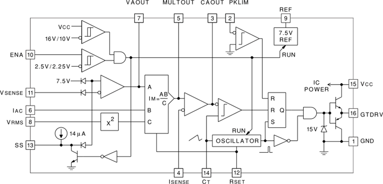
UC3854 Controlled Power Factor Correction Circuit Design. PHILIP C. TODD. ABSTRACT. This Application Note describes the concepts and design of a boost |
|
Circuits for power factor correction with regards to mains filtering
In practice this will require the addition of a Power Factor Corrector (PFC) at the input of many types of mains operated electronic equipment for example |
|
Power Factor Correction (PFC) Handbook
pdf. SCILLC reserves the right to make changes without further notice to any products herein. SCILLC makes no warranty representation or guarantee regarding |
|
Vishay
A large capacitor at the output does not affect the power factor but is good for smoothing the DC voltage. An additional advantage of PFC circuit is the |
|
Eaton
The passive PFC circuitry uses only passive components — an inductor and some capacitors (Figure. 1). Although pleasantly simple and robust a passive PFC |
|
Digital Power Factor Correction using XMC4400
12 juin 2013 The implemented PFC circuit is designed to operate in Continuous Conduction Mode (CCM). The current in the inductor never reaches zero in a ... |
|
Design of Single Phase Boost Power Factor Correction Circuit and
power factor corrector. Then I calculated and designed the PFC circuit and the ACM controller applied in the first level charging of EVs. |
|
How to Select the Right MOSFET for Power Factor Correction
3 juin 2013 A PFC circuit block is used to align the input line current with the AC voltage waveforms and in most cases boosts the output voltage to a ... |
|
Power Factor Correction (PFC) Circuit Basics - TI training
A power factor correction (PFC) circuit intentionally shapes the input current to be in phase with the instantaneous line voltage and minimizes the total apparent |
|
Circuits for power factor correction with regards to mains filtering
In practice this will require the addition of a Power Factor Corrector (PFC) at the input of many types of mains operated electronic equipment, for example electronic |
|
INPUT POWER FACTOR CORRECTION IN A SINGLE - CORE
This is to certify that the thesis entitled “Input Power Factor correction in a Single Phase AC-DC Circuit Using Parallel Boost Converter”, submitted by Ramavath |
|
Improving the Performance of Single Phase Power Factor Correction
Power Factor Correction Circuit using Parallel Boost Converters” submitted by Miss Huma Khan, in partial fulfilment of the requirements for the award of Bachelor |
|
DESIGN OF SINGLE PHASE BOOST POWER FACTOR
power factor corrector Then I calculated and designed the PFC circuit and the ACM controller applied in the first level charging of EVs And I run the design in |
|
POWER FACTOR CORRECTION (PFC) AND HARMONICS - Janitza
Automatically regulated power factor correction current and voltage circuit Parallel resonant circuit between transformer and capacitors without reactors Fig |
|
Power factor correction (PFC) application notes - Eaton
A passive PFC uses a filter at the AC input to correct poor power factor The passive PFC circuitry uses only passive components — an inductor and some |
|
Three-phase Two-level Active Power Factor Correction Circuit
The former Boost converter connected with the input power side of the rectifier realized power factor correction (PFC) The post Buck converter has the function of |

